An ESP-IDF component for Physical Computing
Purpose
Generic UART functionality for ESP32 systems.
How it is done
To use a UART to communicate with another device, you have to
- create an instance of class GenericUart.
In the class constructor you state
- what UART port you want to use,
- the structure with configuration parameters like baud rate, nr of stop bits etc.,
- the GPIO pin for transmitting signals (TX) and
- the GPIO pin for receiving signals (RX).
Currently there are only two methods implemented:
uart_port_t getUartNum();
std::string readString(int timeoutMs);
Method getUartNum() returns the UART port used in the constructor. It can be used to use low-level transmit and receive functions directly.
Method readString() receives all available bytes from the UART. The timeout for the receive operation must be specified.
Where to find it
generic_uart is published on the ESP Registry at https://components.espressif.com/components/elrebo-de/generic_uart.
The source code can be found at https://github.com/elrebo-de/esp_generic_uart.
How to use it
As an ESP-IDF component generic_uart must be included into idf_component.yml as a dependency. As usual this can be done by executing this command:
idf.py add-dependency "elrebo-de/generic_uart^1.0.2"
Now you can include generic_uart.hpp and use the GenericUart class in your program.
The first parameter to the constructor is the tag used for logging as a std::string.
The second parameter to the constructor is the UART port number as a uart_port_t value.
The third parameter is the address of a UART configuration structure. The structure uart_config is of type uart_config_t and defines these items:
    uart_config_t uart_config = {
        .baud_rate = 115200,
        .data_bits = UART_DATA_8_BITS,
        .parity = UART_PARITY_DISABLE,
        .stop_bits = UART_STOP_BITS_1,
        .flow_ctrl = UART_HW_FLOWCTRL_DISABLE,
        .rx_flow_ctrl_thresh = 0,
        .source_clk = UART_SCLK_DEFAULT,
        .flags = {
           .allow_pd = 0,
           .backup_before_sleep = 0,
        },
    };
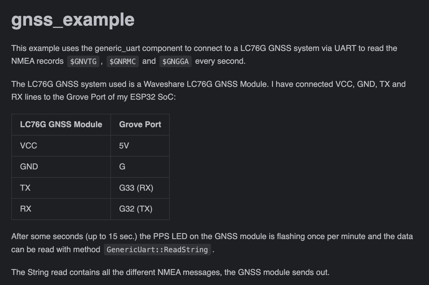
Here the UART to receive data from an LC76G GNSS Module is defined:
// set UART configuration
const uart_port_t uart_num = UART_NUM_2;

uart_config_t uart_config = {
    .baud_rate = 115200,
    .data_bits = UART_DATA_8_BITS,
    .parity = UART_PARITY_DISABLE,
    .stop_bits = UART_STOP_BITS_1,
    .flow_ctrl = UART_HW_FLOWCTRL_DISABLE,
    .rx_flow_ctrl_thresh = 0,
    .source_clk = UART_SCLK_DEFAULT,
    .flags = {
        .allow_pd = 0,
        .backup_before_sleep = 0,
    },
};
// we do not use the TX pin, because we are only reading from RX

// M5STACK CORE2 V1.1
const int uart_tx_pin = UART_PIN_NO_CHANGE; // pin 32 used for LC76G PPS signal
const int uart_rx_pin = 33;

gnssUart = new GenericUart(
                 "gnssUart",
                 uart_num,
                 &uart_config,
                 uart_tx_pin,
                 uart_rx_pin
               );
Leave a Reply